The numbers that define a spur gear
Here m is the module (tooth size in millimetres) and z the number of teeth. Two gears mesh only if they share the same module and pressure angle, which is 20 degrees for most modern gears.
| Size | Formula | 20 teeth, module 2 |
|---|---|---|
| Pitch diameter | d = m × z | 40 mm |
| Addendum (tooth above pitch circle) | m | 2 mm |
| Dedendum (tooth below pitch circle) | 1.25 × m | 2.5 mm |
| Outside diameter | m × (z + 2) | 44 mm |
| Root diameter | m × (z − 2.5) | 35 mm |
| Circular pitch | π × m | 6.28 mm |
Centre distance
For two meshing spur gears, the distance between their centres is a = m × (z1 + z2) / 2. A 20-tooth and a 40-tooth gear at module 2 sit 60 mm apart.
Why the tooth shape matters
Real gear teeth follow an involute curve, which keeps the speed ratio constant as teeth roll over each other. Straight-sided teeth look similar but run rough and wear quickly. With a 20 degree pressure angle, gears with fewer than about 17 teeth also need care to avoid undercutting the tooth root.
The example gear
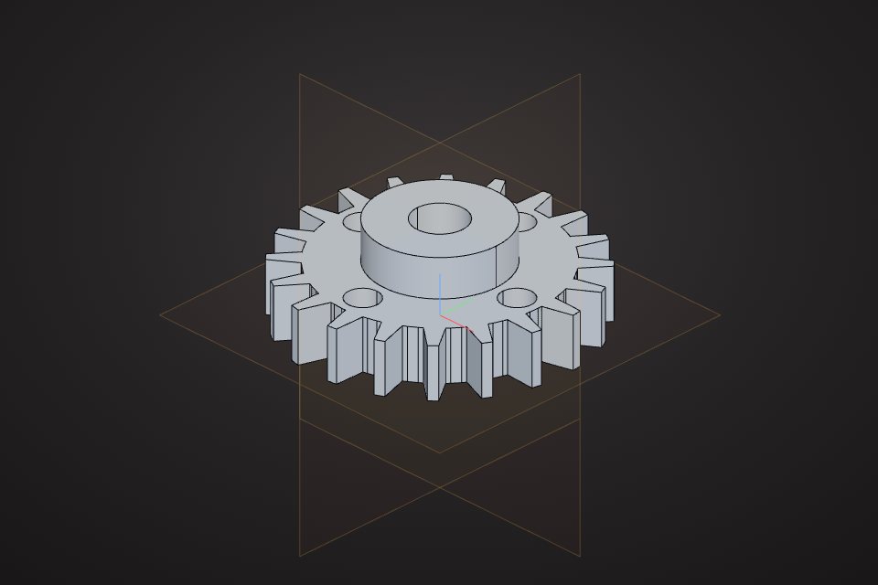
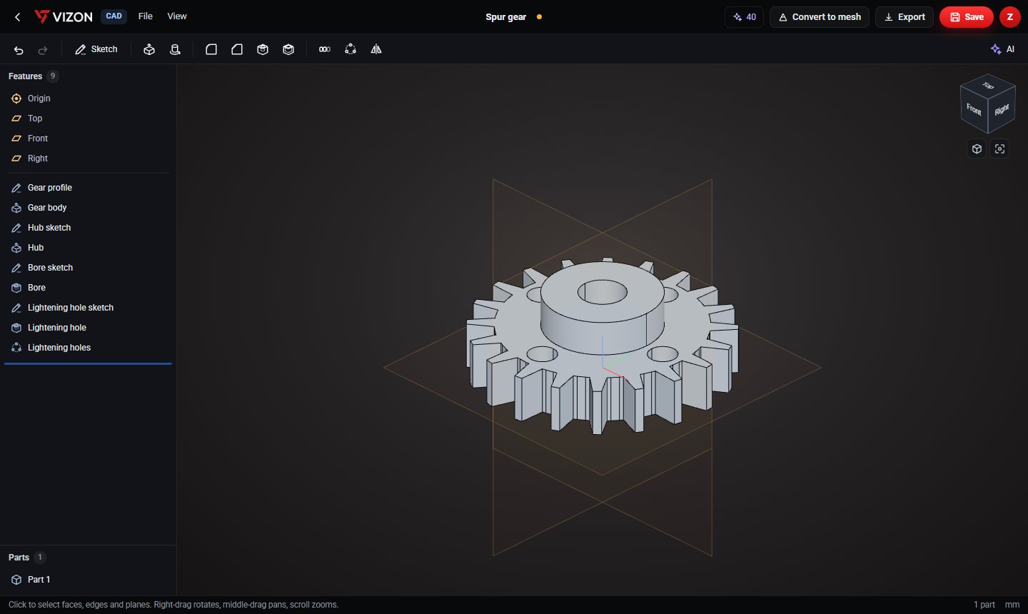
Our 20-tooth, module 2 gear is built from a tooth outline sketch, an 8 mm extrude, a raised hub, an 8 mm bore and four lightening holes made with a circular pattern. Its teeth are a straight-flank approximation: fine for prototypes, mock-ups and display, but swap in an involute profile before using it in a working gear train.
Printing gears
- Print gears flat so the teeth are built from full layers.
- Leave about 0.2 mm extra clearance in the bore for the shaft.
- Use module 1.5 or larger for FDM printing; very small teeth lose their shape.