The four rules at a glance
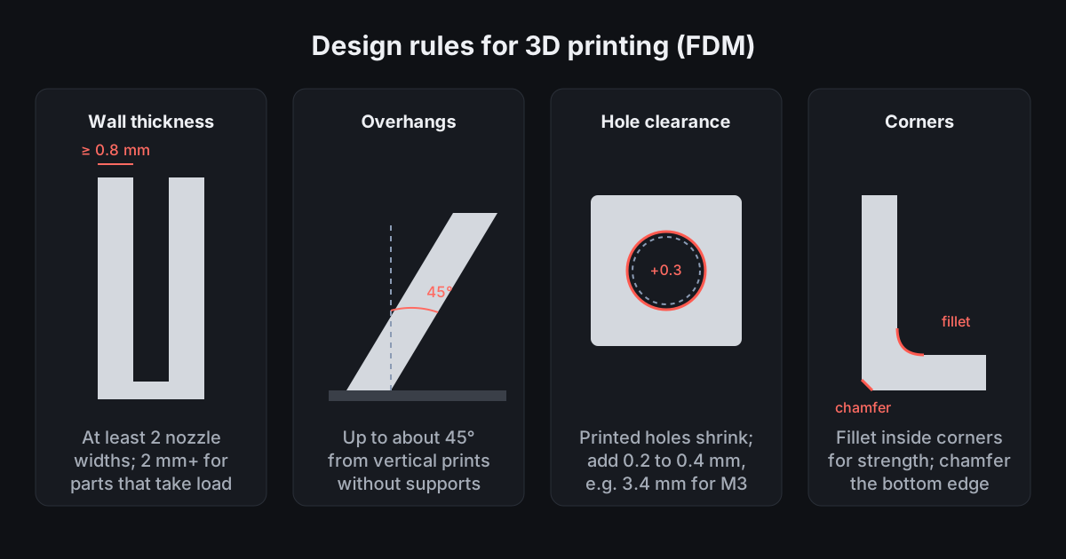
1. Make walls thick enough
A wall should be at least two nozzle widths, so 0.8 mm with a standard 0.4 mm nozzle. Parts that carry load or hold screws work better with 2 mm or more. Thin walls print as a single wobbly line or not at all.
2. Respect the 45 degree rule
Each layer needs something underneath it. Surfaces up to about 45 degrees from vertical print cleanly without supports; anything flatter sags. Chamfers instead of flat overhangs, and teardrop shapes for horizontal holes, avoid most supports.
3. Give holes clearance
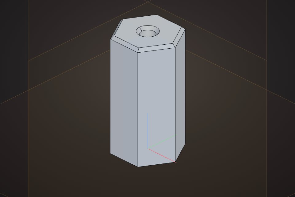
Printed holes come out slightly smaller than designed. Add 0.2 to 0.4 mm to the diameter, or use standard clearance sizes such as 3.4 mm for M3 and 4.5 mm for M4. For sliding fits between two printed parts, leave 0.2 to 0.5 mm of gap.
4. Round inside corners, chamfer the bottom
Sharp inside corners concentrate stress, so a small fillet makes brackets much stronger. On the bottom edge, a 0.5 mm chamfer hides the slightly squashed first layer, often called elephant foot.
Think about orientation
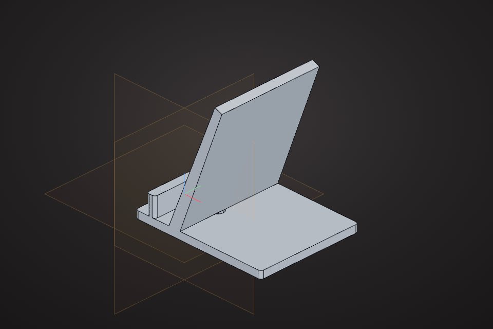
Printed parts are weakest between layers. Orient the part so the main load runs along the layers, not across them. A bracket printed lying on its side is far stronger than one printed standing up.
Example: a printable enclosure
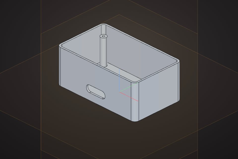
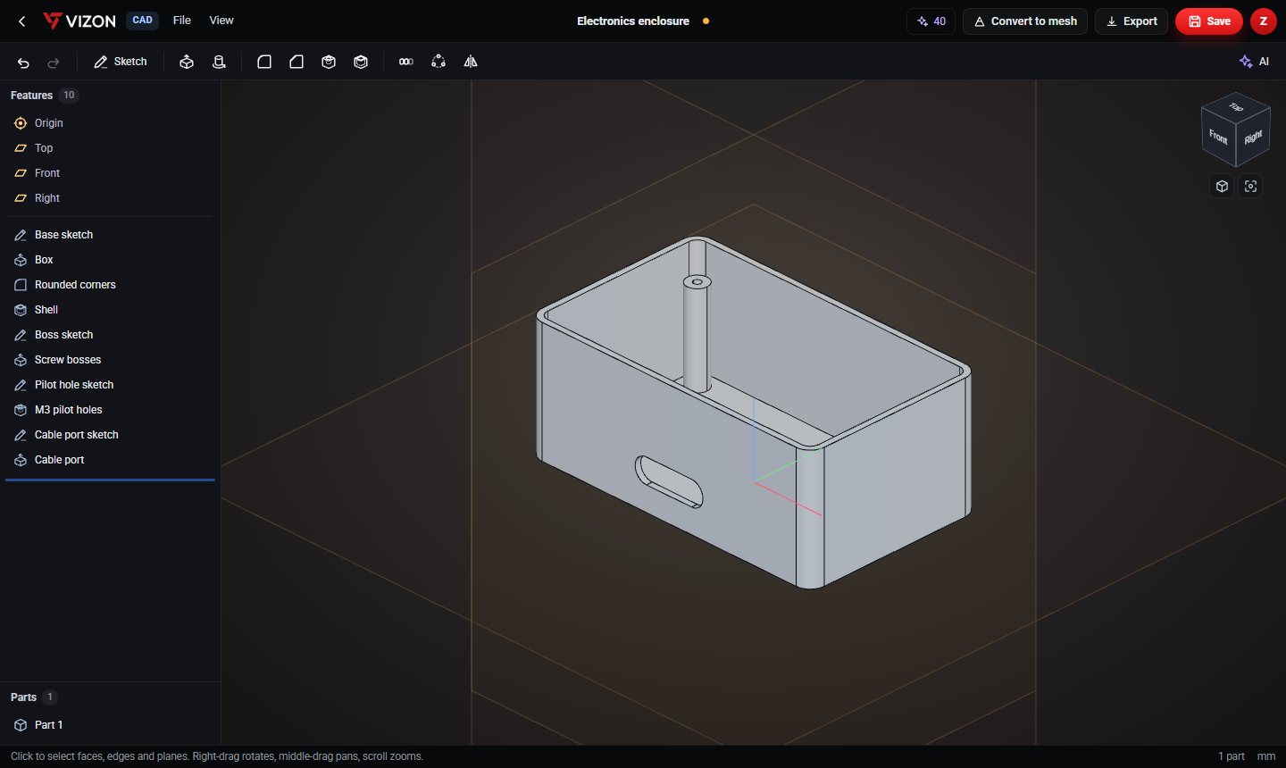
The enclosure in the VIZON model gallery follows these rules: a shell feature gives even 2 mm walls, the vertical corners are rounded, screw bosses have 2.5 mm pilot holes for M3 screws, and the cable slot is a rounded stadium shape that prints without support.
Why parametric CAD suits printing
You rarely get the fit right first time. In parametric CAD a too-tight hole is one number: change 3.2 to 3.4 mm, rebuild, and export a new STL. VIZON CAD exports STL in millimetres with Z up, ready for any slicer.