What we are making
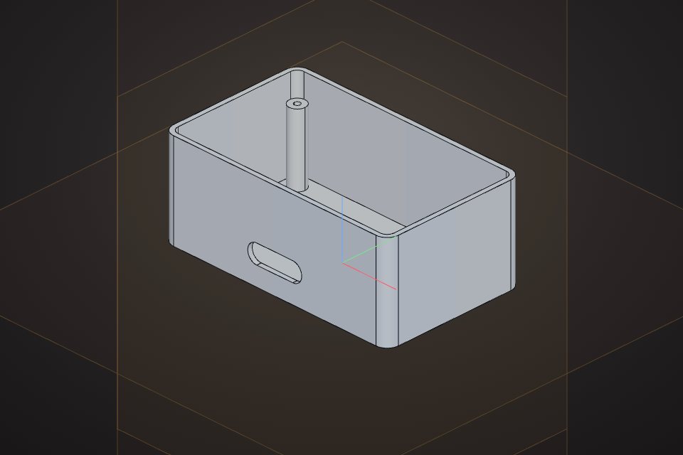
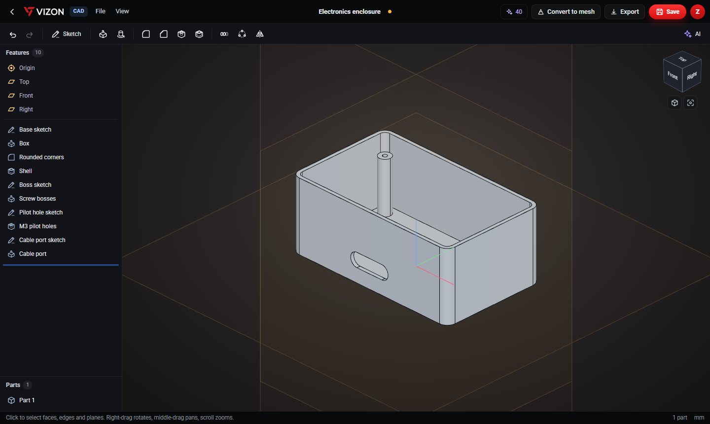
A 100 x 60 x 40 mm open-top box with 2 mm walls, 5 mm rounded corners, four screw bosses for an M3 lid, and a slot for a cable. It takes ten features.
Step 1: the outer block
- Start a new CAD part and sketch on the Top plane.
- Draw a centred rectangle 100 x 60 mm.
- Extrude it 40 mm. This is "Box".
- Add a Fillet of 5 mm to the vertical edges for rounded corners.
Step 2: hollow it out
Add a Shell feature with 2 mm thickness and remove the top face. The box becomes an enclosure with even walls everywhere, and the rounded corners carry through to the inside.
Step 3: screw bosses
- Sketch on the Top plane, offset 2 mm (the inside floor).
- Draw four circles of 3.5 mm radius at x ±42, y ±22.
- Extrude them 30 mm with "add" so they join the floor.
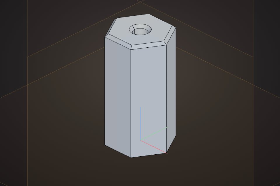
- Sketch four points on top of the bosses (Top plane, offset 32) and add a Hole of 2.5 mm, 20 mm deep: the pilot holes for M3 screws.
Step 4: a cable port
Sketch on the Front plane, offset 30 mm (the outer face of the front wall), draw a slot 16 mm long with 4 mm radius, and extrude it 10 mm into the box with "remove".
Change it for your board
This is where parametric CAD pays off. Need a bigger box? Change the 100 x 60 rectangle in the first sketch, move the boss circles, and everything else follows: the shell, the fillets and the holes. Need thicker walls for a stronger print? Change the shell thickness.
Or describe it to the AI
In VIZON you can type "an electronics enclosure 100 x 60 x 40 mm with 2 mm walls, open top, rounded corners and four M3 screw bosses" and get the same kind of feature list to refine.